refurb

Let’s Refurbish a Van – Part 8: Hood Scoops (By Andy)

A post by Andy

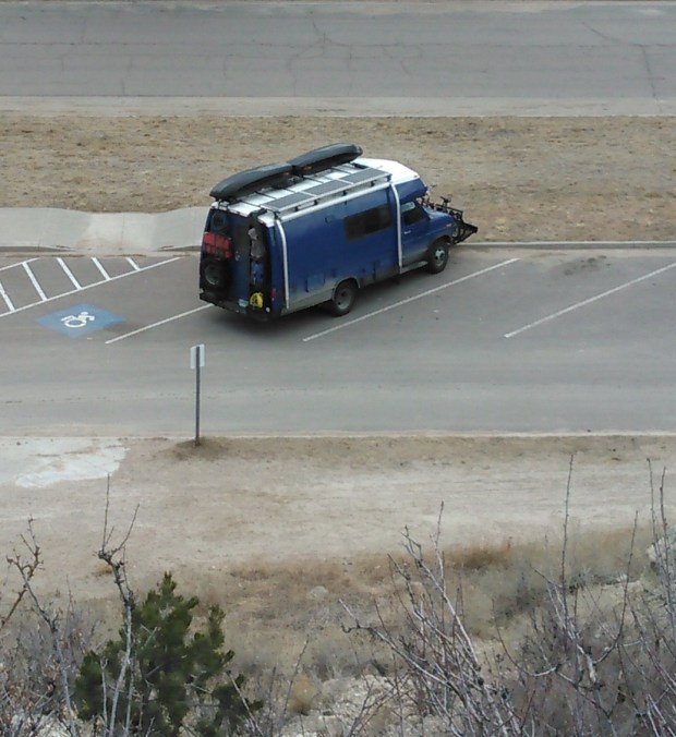
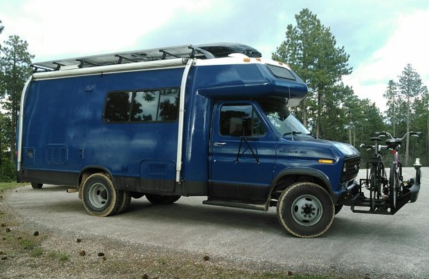
{Modified the title theme some. We think of ourselves much more as a big van than a small RV. I now want to start prefacing this and future posts to be more representative of our self-image.}

So, to the meat of the subject. I just finished our hood scoops! Why did I make hood scoops? Well, for one, they look pretty cool and I needed a prominent place to put my new go-fast emblems that I ordered from Amazon.

KIMG0530

Mainly, we are trying to get as much power out of the engine so we can get our heavy old self up the high steep hills. In that vein, I have been playing with the spark timing, carb mixture, and intake airflow. By tweaking and adjusting these parameters we are working to get the most power and efficiency out of our old engine. Specifically, advancing the timing can get the engine to produce more power, but too much spark advance causes engine problems—pinging and preignition. If the engine is cooler, one can run with more advance. Another way to look at it is that with a given timing advance, if the engine and intake air get hotter, then the timing is too far advanced.

Maybe a side note about my “go-fast” emblems. Car companies try to sell cars. Sometime fancy cars come with racing stripes, cool graphics, and badges on the side about engine stuff. A joke among car people is the question “How much horsepower do the stripes add?” The answer is, of course, none. But… they do look cool. Look around, they are everywhere: M3, AMG, Hemi, 440, HiPo. The only thing the badge or stripes could actually do is add an immeasurably small increase in drag, or some unneeded paint weight. They are simply for the people in the car next to you. All the same, they look sporty, so I bought some that state the displacement of our engine and say it is “High Performance”. What I’m saying here is they do nothing, but they truly do look great!

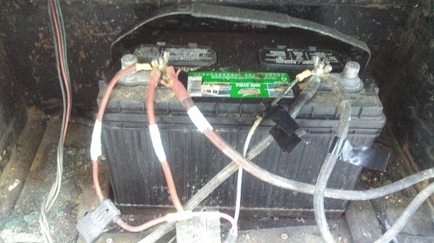
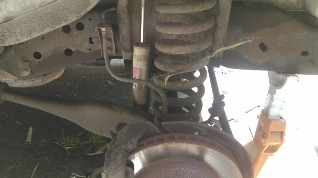
So, I wanted more air to get in and out of the engine compartment to cool the engine, and have the air flowing into the air cleaner be as cool (and dense) as possible. To make sure I had an understanding of the pre-hood-scoop environment, I first taped the probe end of my digital temperature gauge to the air cleaner. Over a few weeks in different driving conditions and different altitudes, we took notes about the temperature measurements of the air cleaner and air filter. You can see the wire to the probe, and the tape holding it in one location.

KIMG0451

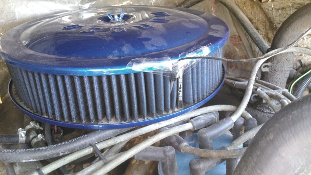
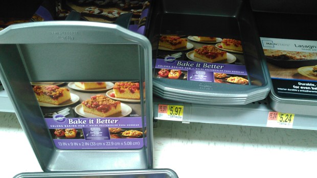
Overall, we are in the 150º–160ºF range under the hood after the engine gets warmed up and when the ambient temperature is in the 70º–80ºF range. So, to get more outside air in and more inside air out we need some kind of venting. I looked online, and $50+ plastic vents and scoops can be found, but they were not really van-sized, and seem flimsy. Metal ones can also be found, but are more expensive, and again, really don’t fit. Apparently there is an untapped market of people who want to mod 1985 Ford vans! (Investors be wary—the market may be small.) I finally hit on the idea that rectangle cake pans are about the size I wanted, and they are inexpensive, and they are made of metal designed to withstand 500ºF+. Going with this thought, while we were camping in El Malpais National Monument, I made some cake pan-sized cardboard mockups and spray painted them with a blue that I had.

Test fitting…

I thought that looked good, so a few days later when we were in a town, we got some cake pans.

KIMG0454

KIMG0455

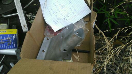
One morning, a few weeks later, when we where camping at the Great Salt Lake, I got out the pans, tin snips, sandpaper, and primer, and got to work remaking our sweet cake pans into even sweeter performance hood scoops (please note the word play).

Here they are.

Test fitting.

We stashed them away for a bit and traveled onward. Another week later we had a free day while visiting our friends the Higdems in Kimberly, ID. I measured, moved, marked, measured, and measured and marked again. Then I started drilling holes in the hood.

Lots of little holes now!

After fitting and drilling the mounting holes, I now knew what piece of the hood (bonnet, for any Brits out there) to cut out. Out with the jig saw.

Another side note here: When putting the Turtle together, we set ourselves up with a few DeWalt cordless tools and the battery charger that plugs into a 12V cigarette lighter. The tool charger is now wired to our solar-charged batteries, so we are using the sun’s energy to drill, cut, and modify our hood. It feels fun to know that when working on projects such as this!

For the final install, I put down a small bead of RTV sealant, aligned the scoops, and screwed in the 6 screws per scoop that I had already pre-drilled. After the RTV cured a bit, I got out our boat paint and went at it.

Included above is, obviously, a photo of what Scout and Gracie were doing at the time. A few days later, at Dave and Ryann’s place, I added more RTV to smooth the transition and put on more paint to finish it all off.

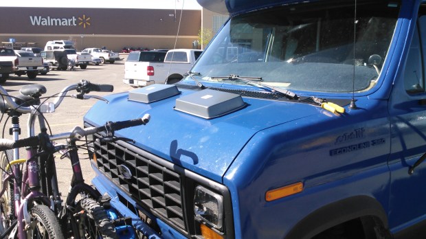
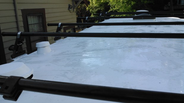
All finished now, after the last painting and with the great go-fast badges installed.

We should call this the conclusions section of the post, for you science people out there. Well, they have been on now for a week, and we don’t move fast, so we have only driven a few hundred miles. We will need to collect more data, but so far the maximum under-hood temperature we have seen in 135ºF, and most of the time it has been in the 100º-120ºF range (and we are actually in hotter weather than when we took our non-hood scoop measurements). We have also driven through crazy heavy rain and, as expected and hoped for, the small amount of water that enters through the scoops has no adverse effects on the engine. Generally, a pretty solid success, and I have since advanced the ignition timing just a bit with no pinging.

Oh, maybe a cost breakdown. The sum total of the cake pans, primer, quantity of screws, RTV, and paint used is less than $20. The go-fast badges were $11 each. Dave suggests I sell it as “The whole project was less than 45 dollars.” I think I shall adopt that tract!

All that for less than 45 dollars!!!

Let’s Refurbish a Van – Part 7: Our Batteries Phase 1 (By Andy)

A Post by Andy

{Note: The work detailed in this part of the post was completed over the summer of 2015, before we moved into the Turtle. I am just getting to writing the post now.}

So, we like to have our computers run, have lights, have the controls for our fridge work, have a charged Wi-Fi hotspot, and have our furnace fan powered to keep us warm. For all this we need electricity, and since we want to be off-grid, we need batteries. We started with this:

HouseBattery

If you are familiar with the Turtle, this compartment is behind the largest access door on the passenger side- the door with the vent in it. In the following photo, I put in a dotted line where the plane of the floor on the inside intersects the compartment.

firstbattery_floorline80

The walls of the compartment above the floor line are plywood, and bump up under the couch inside. The sides and bottom below the line are made of heavy steel. I have deduced the compartment was originally designed for a generator, as there was old 120V AC wiring running to it, an unconnected fuel line that ran into the back, and the door vent.

gimpprocessedimage95

I had a hard time figuring out what all the wires were hooked to, as it was a bit haphazard in the compartment. In the above picture, (1) is a port that goes outside, below the floor of the Turtle. The wires there threaded out of the box, ran a short distance under the Turtle’s floor, then threaded up through the floor to the old inverter. There is a second hole (2) that the wires from the old 100W solar panel and the wires between the battery and main 12V distribution panel were run. (3) is the unused electrical box that had 120V AC wires run to the compartment where the shore power cable is housed.

Maybe I should back up a bit and throw out a few concepts and definitions and explanations for the terms we will be using.

  • Battery: A thing that stores electricity in chemical bonds. Here, we are just referring to 12V lead-acid batteries.
  • 12V/12VDC/DC: 12 Volt Direct Current (DC). This is what cars use for their electricity for headlights, the radio, starting, etc. It is the kind of power all the batteries we talk about will produce.
  • 120v: 120V Alternating Current (AC). This is what is in your house and in businesses you know, the typical wall plug Amy and I look for at restaurants to plug our computers into. It’s generally 120, 121, or whatever it takes.
  • Current: The flow rate of electricity.
  • Voltage: The force pushing the electricity through the wires.
  • Inverter: An electrical box that changes 12VDC to 120VAC. It changes car electricity to house-hold electricity. This is so we can plug our AC computer cords into our DC batteries.
  • Converter: An electrical box that changes 120VAC to 12VDC. The opposite of the above—pretty much a garage battery charger that you use to get your car started after you leave the lights on.
  • Charge Controller: An electrical box that changes the output of the solar panels into DC voltage, hopefully charging the house batteries.
  • House Battery: Now, I probably use this too freely. When I talk about house batteries, and I mean batteries dedicated to our living compartment. If I say house (or household) electricity, I mean 120 V AC. Got to figure this out… but, house batteries are 12V batteries separated from the car system, and dedicated to lights and heat and powering the inverter in the house part of a van. One should be able to run these dead flat, and the car will still start, as they are fully independent circuits.
  • Starting Battery: The batteries under the hood, used for starting the car, sparking the gas when the engine is running, running a radio (if you had a functional one), and lighting the headlights.
  • Shore power: Kind of a boat term, but a source of 120V AC electricity you can plug into. When you pull up at a friend’s house, and pull out your extension cord, and plug into their electricity, they are your “shore power”. (Thanks Alex and Julie, Kari and David, Connie, Mag and John, Dave and Ryanne, Mike and Becky, Blake and Martha, Roger and Mary, Chris, Dad…)

Now, back to the good stuff! To start the battery box rebuilt and modification, I first labeled the wires and removed the old battery. I then cleaned the compartment with baking soda and water to neutralize the sulfuric acid and prevent further corrosion. Lucky, the metal compartment is super stout, so it was still in great shape. As usual, after a final thorough cleaning,  I caulked the seams and painted the compartment with black Rustoleum. I can’t find a picture of the completely empty, cleaned and freshly painted compartment, but trust me, it looked good!


After getting the compartment beautified, I cut and painted a plywood plate to fit into the bottom, bolted and glued it to the metal base of the box, and mounted battery trays to it. I painted up everything with oil-based paint and used stainless steel hardware to affix everything.

Since we had just gotten the Interlux blue boat paint, I practiced the painting technique on the top surface of the plywood base, so it is the same shiny blue as the Turtle exterior. In the following photos, you can see the two new Fullriver 115Ah 12V DC sealed AGM batteries that we started with in there, but just patched into the cleaned up existing wiring we are reusing at this point.


I decided to go with Absorbed Glass Matt (AGM) batteries. They cost a bit more than flooded batteries, but they do not spill, they will not develop corrosion at the terminals, and can be mounted sideways, if that configuration seems important. Additionally, they do not require venting, so they can be safely installed inside the living compartment, if that is necessary. Here is the site. We have been happy with this choice, and as you will find out in future posts, choosing AGM sealed batteries will allow us to make some future cold-weather modifications.

As to wiring, I was just starting to adopt the boat convention for new circuits and runs I would rewire. The convention is as follows: For 12VDC, yellow is ground, and red is positive. For 120V AC, the wires are white, black, and green for ground. Examples of the wires are here:


The reason behind adopting this convention is that at a glance, you can tell which circuit they are supposed to be wired to. Additionally, the boat 120V cable is stranded, as opposed to the household solid copper wire. Stranded wires should always be used in a vibration environment. Logically, then, a van should have no solid copper wires (though most RV builders do actually use cheaper solid copper for the 120V runs). As you might have observed, we have concluded that one should think of their van as a boat, and look to boat paints, wires, latches, and hardware for the upgrades and work. Though the boat cable is a little more expensive, it is paired and tinned for corrosion resistance, and gives a real nice finished look. Additionally, it can be purchased in any gauge.

So, at the end of our Phase 1 battery configuration we had our two new AGM batteries with a combined storage of 230Ah at 12V installed and secured, with the connections cleaned up. With this battery pack, we simply used the old converter to charge them when we were connected to shore power, and the old inverter to make our 120V for our computers when off-grid. At this point in our journey I also had just finished the install of our 300W of solar to charge the batteries (we will cover the panels and solar charging and solar controller in a different post).

That’s Phase 1 for you!

Let’s Refurbish a Van – Part 6: Roof Rack (by Andy)

A post by Andy

{Note: The work detailed in this post was completed over the summer of 2015, before we moved into the Turtle. I am just getting the time to write the post now.}

So, we have stuff to carry. And we want a place to store our solar panels. And we want to stay cool. And, if possible, look cool. So, we need to put together a roof rack…

Here are a few pictures of the old RV when we got it. It had an aluminum ladder that was old and worn, along with the typical RV aluminum tube luggage rack at the back- all bits with some of the mounts loose. We also had a big plastic storage box bolted to the top, but it was cracked and would certainly leak. As you can see, there was also one solar panel and a mount for what I’m pretty sure was a TV antenna. Good stuff, but it was all pretty worn, as it had all traveled for close to 30 years and more than 250 thousand miles.


We wanted our rack and top equipment to do a few things for us:

  1. Have a dry and accessible place to store camping and fishing and other fun gear, out-of-season clothing, and some spare parts and equipment.
  2. Have the rack removable, so we can maintain and fix the roof when the need arises.
  3. Have a location to mount the planned solar panels.
  4. Design the rack to provide us shade.
  5. Have a system that we can change, add more solar to, move things around, etc.
  6. Be able to fill and seal up all the holes prior people made when mounting things to the roof, and have a system where moving forward we will not be drilling into the roof any more.

Anyway, roof racks look great! I hear they can be useful too. In truth, we have pretty limited room and storage inside, so having a bit of room up top for our extra supplies and garage-like stuff was essential for a successful voyage.

So, to the step of getting the old stuff off and sealing up the holes. Pretty much unbolt the bolts and pry everything else off. I then used fiberglass impregnated epoxy body filler for all the big holes (I love epoxy!), maybe adding wire to support it as it cured. I then added Geocel Proflex on the seams. I read about and tried a few things, but to date, it is my go-to for exterior sealing. Here is a link.

For the (many) smaller holes, I would first clean and fill with the Geocel, then screw in a stainless steel screw the size of the hole, then cover the head of the screw with another layer of Geocel. It is a technique I read about on the internet, and it seems to have worked well so far. Again, it is not worth buying any hardware but stainless or grade 8. It does cost a little bit more, but use the savings you get for doing this yourself to get the good hardware. Plus, you don’t have to worry about some interior rust and redoing the work down the road. After sealing the holes, I put down Rustoleum on all the modified spots. The following pictures show the antenna hole through the roof, and some of the removed parts scattered in the yard.

We were lucky enough to have a friend who worked for Yakima who gave us a VIP discount card for one purchase. With the card, we got 12 A1 rain gutter towers, 6 78″ crossbars, 12 wide body rain gutters, end caps, two 12-peice lock core sets, a Loadwarrior basket, and some cargo nets. A truly impressive amount of wonderful Yakima pieces at a great savings. Boxes and boxes of sweet components!

From REI, Amy and I used our one-item 20% member discount and each of us bought a Skybox Pro 12, shipped to the Portland REI for free. We got the long and narrow boxes to configure end-to-end, and not take up too much roof area width-wise. We effectively have the roof racks for 4 vehicles, all to put up top the Turtle. It added up to a lot of initial investment, but it has been working well, and added an important comfort to be able to store a reasonable amount of things to make our small world flexible, and I think it actually has a sleeker look being made from components—as opposed to a custom-fitted rack. Since we were doing all the work ourselves, we decided to invest a bit more on some nice new hardware. After popping down to REI and loading our new Skyboxes (in their own boxes) onto the top of the old Scout, we stopped for a bite in downtown Portland. Seems fairly reasonable to me, but I imagine to some people we made a sight…

The sky boxes, along with the other hardware, sat in the house for quite awhile. After stripping and sealing the roof, it was only logical to finish painting the Tutle blue, then do the white roof paint, and then finally get to the point where we could install the new roof rack. Consequently, this is what our place looked like for quite an amount of time. (As you can see, our front room was used to store a number of Turtle parts until they were ready to install.)

The pictures are few here, but after most of the painting was finished, I mounted the wide body mounts. I measured, marked, measured again, checked, and had the geometry figured out. On the corner of the Turtle roof, I would drill my two holes, fill with Geocel, cover the mounting surface with Geocel, align the bracket, screw in two (you guessed it) stainless steel lag bolts, then cover the seam and outside with Geocel. After it all cured, we repainted with the Interlux. It looked nicer with the black brackets and shinny bolts before the sealant and paint, but I didn’t want to risk it. And, just so you know, the asymmetric spacing along the length of the roof is due to needing to align the crossbars so they will not interfere with a roof vent when open, but also allow for the mounting points of the skyboxes. Here are the brackets installed:

kimg0798

It is a nice feeling to know that at any point we could unlock (all keyed alike, now) the 12 towers, unscrew, and remove the whole rack if we had to do some maintainence on the topside. Anyway, the pictures are limited at this point, but following are some involving the tower, crossbar, and rack install.

kimg0804

You might notice that the Yakima basket lost out to the solar panels. The basket is in the storage unit presently, and it would be great to get it up there at some point. When we were building and installing the rack, though, the geometric logistics were far too difficult for the time allocated. Anyway, to install the solar panels, I bolted two pieces of 12′ 6061 T6 aluminum square tubing to the crossbars with stainless steel carriage bolts and nuts fitted through the Yakima Universal Snaparounds.

I picked up used ones super cheap here. By the way, ReRack in Portland are nice people and can save you some money on roof racks, so check them out if you are in the area. Back to topic, after getting the aluminum properly spaced and installed, I then drilled and screwed the solar panel brackets to the the aluminum. That step was a breeze. Solar panels installed, photo taken probably a month in.

kimg0938

As to keeping it all cool. We planned on (and did), paint the roof surface with a couple of coats of Interlux topsides white boat paint. We actually painted the roof vent covers white as well. The assumption is that paint will reflect much of the sun’s heat, and be able to withstand the UV rays. So far, everything looks pretty good up there. We have some cracks in the paint where the caulking we used was not completely cured before we painted (I don’t blame the paint, we had time constraints), so we have some washing and fixing of some seams to do. Otherwise, all looks pretty good. A common approach for keeping a bit cooler is to have a couple of roofs, effectively carrying your own shade along with you.

The above old-school Rovers have a second roof with an airgap for passive cooling in the hot sun. (Side note, did anyone notice the tall skinny tyres the rovers are running on?) With the spacing added from the rack towers, and mounting the solar panels and boxes above the crossbars, we have a impressive air gap and continous shade on over 50% of the roof.

Currently, there is a middle strip free for walking, in which I will fit an additional panel at some point, then simply make some cheap synthetic or plywood panels and paint them white to increase our shade to close to 100%. So far, though, we have been to the Badlands of South Dakota in the summer, and have stayed with the ambient temperature with thoughtful venting and minimal electric fans.

To me, the goal is not to be cooler than the outside, all we need to do is not be hotter than the ambient temperature in all kinds of weather.

kimg0184

Oh, almost forgot, we want to access the roof! We need to clean the solar panels, get stuff into and take stuff out of the boxes, check on all the paint and seals, and most importantly, be able to climb up and yell with arms outstretched like you are in a movie! Anyway, the ladder…

We actually bought a car roof rack ladder as a start. The almost $200 ladder (seems crazy) was well worth the money, in the time saved. It always feels pretty weird to buy something new, remove it from the box, then start cutting it right away. So, the ladder, welding, adding more rungs for the proper length, and fixing the folding function.

Some close-to-final pictures here. We started with a 9-rung foldable ladder, and ended with a 12-rung rigid ladder that bolts to the bumper and the top rack. Again, it was designed to bolt to the bumper and rack, so it is removable…

I’m pleased with the removability of the ladder, because we crushed it a bit when we backed into a tree one day, about a week after it was finished and installed. The ladder was subsequently unbolted, straightened, and remounted. From the side, it now does have a bit of ripple (below the designed joint and by the spare tire)—this is what we call life.

kimg0186

To sum up a bit, up in the boxes right now we have a few fishing poles, extra wire and parts and unfinished projects, cloth for sewing projects, extra window insulation, snow shoes and masks and fins, river tubes, my old tent. A pair of driving lights I have yet to wire up. Some cheap speakers I plan on installing in the doors. You get the picture. We call it our attic.

img_1863

We have a completed rack now. It holds our solar panels, is our attic, and still has room to exapand.


Let’s Refurbish a Van – Part 5: Suspension (By Andy)

A post by Andy.

{Note: The work detailed in this post was completed over the summer of 2015, before we moved into the Turtle. I am just getting the time to write the post now.}

We wanted a little more ground clearance, fender and frame spacing for the taller tires, and a good, safe ride. We initially hoped to find an off-the-shelf lift kit. . . no soap. People make them for Ford trucks and Broncos, nothing for 80’s vans. I suppose that makes sense; the van market must be pretty small. So I guess we’ll just have to design and install a complete suspension overhaul and customization ourselves. This is where we started…

KIMG0366.jpg

In the front we have what Ford calls a twin I-beam suspension with what I infer is an aftermarket sway bar, and the rear is just a simple leaf spring configuration, though there are functional aftermarket Firestone airbags that have been added.

Let’s address the rear first; that is comparatively easy. We found some 2″ lift blocks from Action Van (http://www.actionvansuspension.com), that fit between the axle and leaf spring. Action Van actually makes full lift kits, but only for ’92 and newer Ford vans. Lucky, the rear suspension was the same, so we were able to use their blocks for the back.

With some breaker bars on the end of the socket wrench and a little groaning, the blocks were pretty easy to install. Lots of jacks and heavy-duty jack stands were employed in this step! Here is a poor photo of the suspension when I was starting the modification.

1433618343139.jpg

Here is a photo of the installed blocks. Always remember that it is a good idea to drive a bit and then retorque all the bolts for suspension components after making changes- things can settle under the vibration.

kimg0176

After adding the lift blocks, the rear airbags were adjusted by cutting, drilling, and painting 2″spacers from hollow square tubing and bolting into place between the axle and bottom of the air bags with new grade 8 hardware. Sorry for the bad photos (at the time, the important thing was to get stuff done, so the documentation suffered), but what you can see in the following is the original airbags and the blocks and hardware cut, drilled, and painted.

And a current photo of the final installed version- a little dirty, as we have been trekking about for a little over a year now.

Pretty straight-forward modification, and after a few thousand of miles everything is very solid.

cropped_1

Now the front suspension. The modifications needed were: 1) taller coil springs 2) adding air bags 3) fitting the new shocks 4) dropping the sway bar 5) dropping all 4 I-beam pivot points 6) replacing all the suspension bushings in the process.

I was able to find taller MOOG coil springs and front airbags, cranked everything apart, and got those pieces installed.

You can see that at this point with the added spring height but no change to any of the I-beam pivot points, the camber is extreme.

KIMG0371.jpg

The next step was to remove the suspension mounts. This was a true pain, as there were many frame rivets to remove. Depending on the accessability, I would drill, grind, hammer, cold chisel, or simply swear at for long enough to remove. I would consider it a solid success if I came home from work, spent all evening, and got only one removed. I blocked it out, but there were somewhere between 16 and 20. Anyway, after getting the pivot points removed, I made some drawings describing the desired changes needed to drop the pivot points 2″ lower, then took the parts to a fabricator. I weld myself, and made the grill guard, and all other metal modifications on the Turtle, but I wanted really great welds on these parts, so we paid to have someone with more skills do the modification. Plus, it was pretty darn magical to just drop the parts off and pick up the finished pieces a few weeks later. So, some of the suspension pieces back from the welder:

1440187262716

Painting, almost ready to install. I had ordered new MOOG bushings for all the pivot points, so these were installed at this point too.

1440192040722

Except for reusing a few special Ford bolts, the bolts and frame rivet locations were replaced with 1/2″ grade 8 hardware. Some current pictures of the completed front suspension.

Here is a photo of the dropped sway bar pivots with the new greasable bushings installed, again, everything is grade 8 hardware. I never buy anything else (except maybe stainless for chassis fixturing or the interior).

kimg0182

New Bilstein shocks were ordered for all four corners. The stock fit for the rear has enough travel to handle the 2″ lift, so we got the heavy-duty RV ones, and that was easy. We had to calculate the new front geometry to size the front, and went extra fancy with the front shocks and got an external reservoir setup. They look cool! (I ordered them from shockwarehouse.com, part number 25-177480 and 24-184663.)

Here is the front suspension a year into our travels. I was replacing the brake pads, so I took the opportunity to clean everything up, and also paint the hub with Rustoleum. We have had no problems with the suspension thus far.

kimg0047

The lift was added to enable us to have the taller tires, and to have more ground clearance. There have already been a number of cases where we figure we would have likely damaged something on the underside if we did not have the clearance we have. Additionally, with the clearance and narrow tires, we have made it through some pretty deep snow without problems. It has proven to be a successful modification. Plus, it makes the Turtle look cool!

Let’s Refurbish a Van – Part 1: Flooring

Well, it’s been raining virtually nonstop for the last few weeks in Portland, and Sauvie Island seems as if it’s ready to admit defeat and just merge with the Columbia River and call it a day. So I’m working from the island today, appreciating how warm and dry I am inside, and thinking about how just a year ago I was dreaming of this very scenario, feeling like the day would never come!

*Newly-formed lakes and sunken pumpkins on Sauvie Island not pictured. It has been raining so hard, one photo would send my phone right into a bag of rice.

These days, as we sit in the Turtle, eating dinner at the table or climbing up the ladder into our cozy lofted bed, we sometimes take for granted how much work actually went into this project. Because we gave ourselves such a tight deadline, we didn’t have time to stop and appreciate each accomplishment as it was crossed off the list, because there was another line item right below it requiring immediate attention. The moment we crossed one finish line, we’d look up and see there was another lap ahead of us!

IMG_3452A portion of the list. 

If you’re thinking of taking on a similar project, or if you’re just curious how we got from Point A to Point B, here I’ll be discussing our process, and what we learned along the way. I will admit, our experience was made much easier due to Andy’s crazy number of useful skills! But if you’re like me and aren’t handy with welding, car mechanics, woodworking, and wiring lighting (among Andy’s many other contributions), don’t despair! The most inspiring thing about Andy is that when he comes across a job that requires skills he doesn’t have in his personal toolbox, he does research online, buys books, and reads the blogs of others who are skilled in that field. He then gets the needed tools for the job, and just gives it a go. Personally, I tend to get intimidated by new large-scale tasks that feel like they should require a professional. But throughout this project, following Andy’s lead, I found myself feeling empowered and excited to see what I could learn and accomplish. If I can fiberglass and epoxy a floor, anyone can!

KIMG0095The quality of this photo is terrible, but the cuteness is top shelf.

Our first goal in the refurbishment was to strip down the interior of everything we wanted to update. This included nearly all soft surfaces, as the Turtle is 30 years old and these tend to hold on to dirt and odor. . . and the design sensibilities of 1985.

So as it was the first change we made to the Turtle, for this portion of the blog, let’s discuss flooring.

KIMG0023
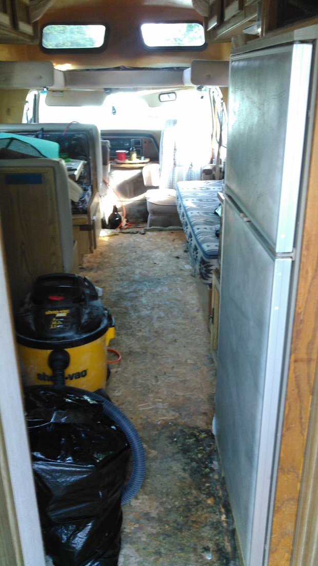
This is one of the only photos we have of the carpet before Andy pulled it out – just a teeny slice visible in the bottom left corner. But you get the idea. 

KIMG0020A bit more carpet shown here. We just got so excited to get started, we didn’t get a whole lot of “before” photos before things started changing!

First, Andy ripped out the carpets and the subsequent one million carpet staples. I’d like to say I’m exaggerating the number, but I kind of am not. I worked on just a 30″x30″ portion and the resulting blisters were highly impressive.

KIMG0050

KIMG0041

Underneath the carpet was the OSB flooring we were expecting to find. Due to its age and thickness, it tended to sag quite a bit when walked on, so Andy proposed reinforcing it with sheets of fiberglass cloth and epoxy. At this point, I’m going to use the pronoun “we” when I discuss our work on this project, because I now am a fully qualified epoxy applier, and proud of it! Though of course Andy did much of the up-front work before training me—but I felt very pleased with myself when I realized that I can now strengthen any old floor I like!

In a few areas, the flooring had rotted out pretty significantly. Ever the optimist, Andy was pleased that it was an easy early indicator of where we had leaks that we needed to fix, before finding out the hard way when the rain hit! So he cut out the soft blackened area and replaced it with another piece of OSB that he cut to fit.

So, in small increments, we 😉 laid sheets of fiberglass cloth over the floor of the turtle and rolled thin layers of epoxy over it with a small roller, eventually covering the full surface area and applying additional layers in the weaker spots. Between each layer, we sanded it down to keep it nice and smooth, as portions of the fiberglass tend to raise up a bit here and there.

IMG_0383Halfway epoxied. (Guess which half!)

It was so smooth and shiny that Andy originally wanted to leave it as it was. Truthfully, it really had a neat industrial quality to it, but as it was going to be our home, I was hoping for something a little warmer. He cared less than I did about this issue, so we agreed to find flooring to install over the OSB.

After researching a number of ideas for the flooring surface, we decided on vinyl stick-on tiles. They’re fairly durable, inexpensive, and if any damage is done to a portion of the floor, we can just pull it up and lay a new one in its place. Considering the fact that we plan to play hard while on our adventures, neither of us wants to tiptoe around the Turtle trying to keep it pristine. But we also don’t want to take all this time just to trash it either! So it seemed like the best route.

The majority of the options we found were square parquet-style tiles, which we liked, but I had my heart set on long planks. After some research, we found exactly what we were looking for at Lowes: cherry “wood” planks with some textured striations to give it a more realistic wood feel. They sell them both by the box as well as individually, and are relatively easy to cut to size.

IMG_1794-001

IMG_1714

IMG_2059

Aside from the fact that the Turtle has some ca-raaazy angles, installation was fairly painless. I’d imagine if you have a more uniform and rectangular vehicle, you’d have an easier time than we did. The Turtle, though, is made up of friendly-looking but unpredictable curves and turns, so both we and the box cutter were put to the test.

But we got it done, and there you have it! Brand new floors. They’ve been holding up great, and with all the rain and mud we’re experiencing out here lately, I’m so appreciating the ease of hard surfaces as opposed to a muddy carpet to clean! And with the recent addition of a few navy runners, it really feels like home.